Isolated network VLANs
By default, bare metal nodes on each Chameleon site share the same local network (shared VLAN and IP subnet). However, some experiments may require more network isolation, which is now supported by Chameleon.
Chameleon’s implementation of network isolation is based on dynamically managed VLANs (network layer 2) associated with user-configured private IP subnets (network layer 3). This means that all network communications local to the IP subnet or the broadcast domain (such as Ethernet broadcast, ARP, IP broadcast, DHCP, etc.) will be restricted to the user-configured network and its associated VLAN. This feature enables a range of experiments in networking and security. For example, this allows running your own DHCP server to configure virtual machines running on bare metal nodes, without impacting other users.
Note
Strong network isolation is provided at network layer 2 only. Even using separate IP subnetworks, any bare metal node can still communicate with each other and with the Internet through the network’s router. We are investigating solutions to provide stronger isolation at network layer 3.
Network isolation works on all nodes, including our low-power HP Moonshot nodes (low-power Xeon, Atom, ARM64).
To use this feature, you will need to create a dedicated network and router. You can use a Heat template, use the Network panel of the GUI, or use the CLI.
Configuring networking using a Heat template
Go to Project > Orchestration > Stacks.
Click the Launch Stack button to open an interactive dialog.
Select URL as Template Source and paste https://raw.githubusercontent.com/ChameleonCloud/heat-templates/master/network-isolation/network-isolation.yaml to Template URL.
Click the Next button to navigate to the Launch Stack dialog.
Provide a name for your stack, enter your password, and set a private IP range, such as 192.168.1.0/24.
Set the first and the last IP addresses of DHCP range.
Important
The first IP adddress in the DHCP range should never be *.1 and *.2. The last IP address in the range must be less than *.255.
Start creating the network and router by clicking the Launch button.
Creating a network using the GUI
To create a Network from either the Network Topology page or the Networks page, click the +Create Network button to open the Create Network dialog.
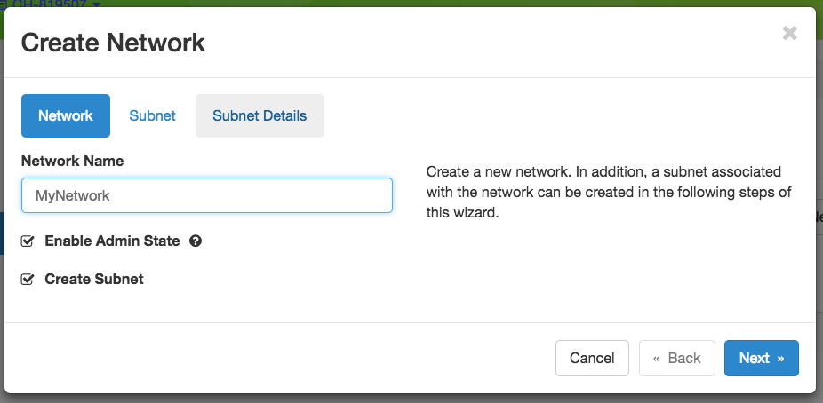
The Create Network dialog
In Create Network dialog, name your network. In general, you will also want to create a Subnet for your new Network, so make sure you have Create Subnet checked. Click the Next button.
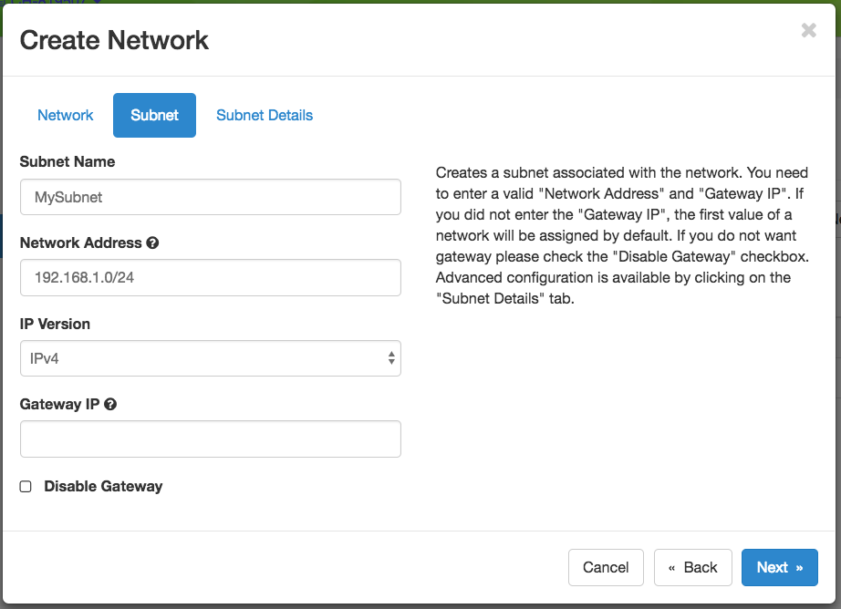
The Subnet tab
When creating a Subnet, you must specify a Subnet Name and a CIDR Network Address that contains a private IP address and a subnet mask length. For example, you may create a Class C subnet with a 24-bit mask by entering 192.168.1.0/24. You may set a Gateway or leave it blank to use the default. Then, click the Next button.
Attention
Do not select the Disable Gateway checkbox!
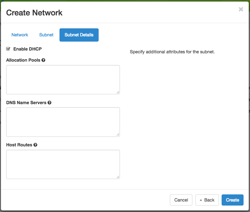
Subnet details
Tip
If you plan to run your own DHCP server on this network, either skip creating a subnet, or uncheck Enable DHCP in the Subnet Details below. Neutron’s built-in DHCP will conflict with your own DHCP server if both are active on the same network. This can also be handy if you’re setting static IPs, and just want to avoid noise in the logs when running e.g. tcpdump.
You may specify DHCP and static Route information at Subnet Details section:
Allocation Pools section allows you to specify DHCP address ranges in the format of
<first address>,<last address>. For example, entering192.168.1.2,192.168.1.100will create a Subnet with IP ranges from192.168.1.2to192.168.1.100.DNS Name Servers section allows you to specify a list of DNS servers.
Host Routes section allows you to specify static routing information for the subnet in the format of
<subnet CIDR>,<router IP address>. For example,192.168.3.0/24,10.56.1.254means all traffic from this Subnet to192.168.3.0will be forwarded to the Router Interface at10.56.1.254.
Note
All three sections above are line separated.
Click Create button and a new Network will be created. Check if the network is created without error.
Creating a router
To create a Router from either the Network Topology page or the Routers page, click the +Create Router button to open the Create Router dialog.
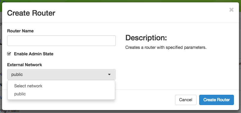
The Create Router dialog
In this dialog, specify a Router Name. Optionally, you may select public as the External Network if you want to have external access. Click Create Router to complete the process.
Adding a router interface
A Router may have multiple Interfaces, each connected to a Network. You may add an Interface to an existing Router by clicking on Add Interface from either the Network Topology page or the Routers page to open the Add Interface dialog.
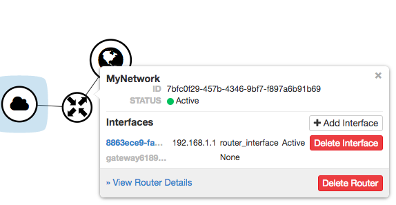
The Router interface in the Network Topology page
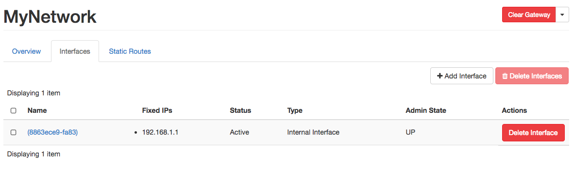
The Interfaces tab in the Router detail page
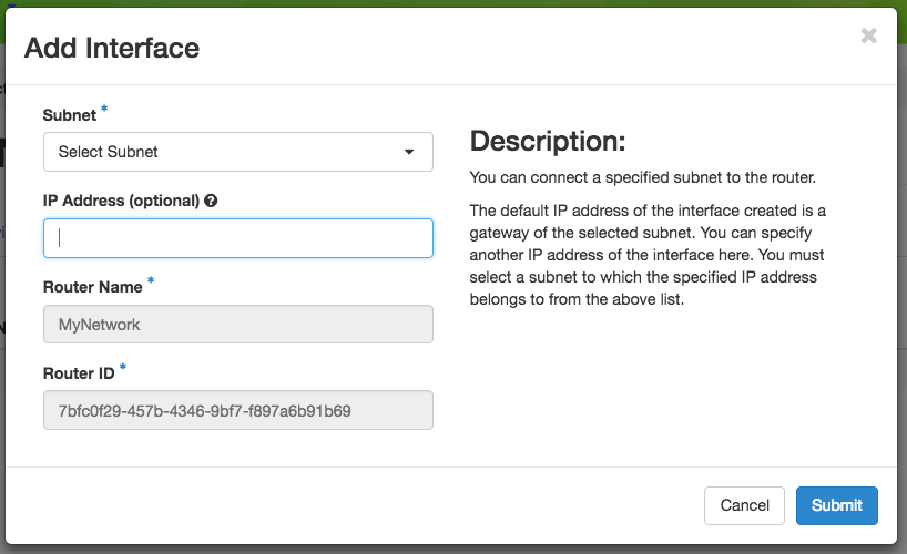
The Add Interface dialog
First, select a network and subnet you have created. You can specify an IP address; otherwise, Chameleon will attempt to assign an IP address automatically. The gateway IP you assigned to the subnet will be automatically picked.
Deleting networking objects
Attention
Network objects such as Routers and Networks must be deleted in the reverse order of which they were created. Objects can not be deleted while other objects are depending on them.
Attention
Before starting to delete network objects, make sure all instances using them are terminated!
Go to Project > Network > Routers, and click on the router you would like to delete.
Go to Static Routes tab, and click on the Delete Static Routes button in the Action column. The Static Routes will be deleted after confirm.
Go to Instances tab, delete the Gateway interface by clicking on Delete Interface button in the Action column and confirm the deletion.
Now you can safely delete the router by clicking on the dropdown on the upper right corner. Then, click on Delete Router. Finally, confirm your deletion of the router.
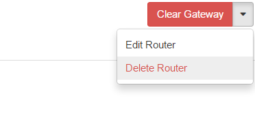
Dropdown for deleting router
Go to Project > Network > Networks, and delete the network by using the dropdown in the Action column. Alternatively, you may delete the network by selecting the network using the checkbox and click on Delete Networks button on the upper right corner. Confirm your deletion to finish the process.
Configuring networking using the CLI
Tip
Reading Command Line Interface (CLI) is highly recommended before continuing on the following sections.
Before using the CLI, make sure you have configured environment variables using The OpenStack RC script.
Note
There are two different ways to get an isolated VLAN network, and they’re not interchangeable:
Create it directly (below) — Neutron picks any available network segment for you automatically. This is the simplest path for most experiments.
Reserve a specific segment via :ref:`reservation-cli-vlan` — use this instead if you need to guarantee a specific VLAN segment (for example, to match one already configured on external hardware), or if direct creation fails because Chameleon has no free segments left at the moment (see the note below). Either way, once the network exists you still configure its subnet and router the same way, as described in this page.
Creating a network
You can create an Isolated VLAN Network using the command:
openstack network create --provider-network-type vlan --provider-physical-network physnet1 <network_name>
The output should look like the following:
+---------------------------+--------------------------------------+
| Field                     | Value                                |
+---------------------------+--------------------------------------+
| admin_state_up            | UP                                   |
| availability_zone_hints   |                                      |
| availability_zones        |                                      |
| created_at                | 2018-03-23T23:45:19Z                 |
| description               |                                      |
| dns_domain                | None                                 |
| id                        | 21ed933c-323d-4708-930c-d5f82c507430 |
| ipv4_address_scope        | None                                 |
| ipv6_address_scope        | None                                 |
| is_default                | None                                 |
| is_vlan_transparent       | None                                 |
| mtu                       | 1500                                 |
| name                      | MyNetwork                            |
| port_security_enabled     | False                                |
| project_id                | d5233415ee0b467baec14cbd2d0e1331     |
| provider:network_type     | vlan                                 |
| provider:physical_network | physnet1                             |
| provider:segmentation_id  | 2018                                 |
| qos_policy_id             | None                                 |
| revision_number           | 2                                    |
| router:external           | Internal                             |
| segments                  | None                                 |
| shared                    | False                                |
| status                    | ACTIVE                               |
| subnets                   |                                      |
| tags                      |                                      |
| updated_at                | 2018-03-23T23:45:19Z                 |
+---------------------------+--------------------------------------+
Note
Note the provider:segmentation_id field in the above output. Each Isolated
VLAN Network requires a unique network segment to operate. There are a finite
number of valid network segments on Chameleon. If you are unable to create a
network because there are no valid network segments available, then you can
create a network automatically by Creating a lease to reserve a VLAN segment.
Once you have created a Network, you may create a subnet with the command:
Tip
If you plan to run your own DHCP server on this network, either skip creating a subnet, or use --no-dhcp instead of --dhcp below. Neutron’s built-in DHCP will conflict with your own DHCP server if both are active on the same network segment.
openstack subnet create --subnet-range <cidr> --dhcp --network <network_name> <subnet_name>
For example, the command:
openstack subnet create --subnet-range 192.168.1.0/24 --dhcp --network MyNetwork MySubnet
will create a subnet with the following output:
+-------------------+--------------------------------------+
| Field             | Value                                |
+-------------------+--------------------------------------+
| allocation_pools  | 192.168.1.2-192.168.1.254            |
| cidr              | 192.168.1.0/24                       |
| created_at        | 2018-03-23T23:50:11Z                 |
| description       |                                      |
| dns_nameservers   |                                      |
| enable_dhcp       | True                                 |
| gateway_ip        | 192.168.1.1                          |
| host_routes       |                                      |
| id                | 8be4e80d-ba49-4cdc-8480-ba43dd4724c2 |
| ip_version        | 4                                    |
| ipv6_address_mode | None                                 |
| ipv6_ra_mode      | None                                 |
| name              | MySubnet                             |
| network_id        | 21ed933c-323d-4708-930c-d5f82c507430 |
| project_id        | d5233415ee0b467baec14cbd2d0e1331     |
| revision_number   | 2                                    |
| segment_id        | None                                 |
| service_types     |                                      |
| subnetpool_id     | None                                 |
| tags              |                                      |
| updated_at        | 2018-03-23T23:50:11Z                 |
+-------------------+--------------------------------------+
To see more options when creating a subnet, use the following command:
openstack subnet create --help
Creating a router
To create a router, use the following command:
openstack router create <router_name>
Your output should look like:
+-------------------------+--------------------------------------+
| Field                   | Value                                |
+-------------------------+--------------------------------------+
| admin_state_up          | UP                                   |
| availability_zone_hints |                                      |
| availability_zones      |                                      |
| created_at              | 2018-03-23T23:56:35Z                 |
| description             |                                      |
| distributed             | False                                |
| external_gateway_info   | None                                 |
| flavor_id               | None                                 |
| ha                      | False                                |
| id                      | 9b5d4516-804a-4c01-9016-3a27fc4197d1 |
| name                    | MyRouter                             |
| project_id              | d5233415ee0b467baec14cbd2d0e1331     |
| revision_number         | None                                 |
| routes                  |                                      |
| status                  | ACTIVE                               |
| tags                    |                                      |
| updated_at              | 2018-03-23T23:56:35Z                 |
+-------------------------+--------------------------------------+
Adding a router interface
A Router Interface can be added and attached to a subnet with the command:
openstack router add subnet <router_name> <subnet_name>
In addition, you can specify an External Gateway for your router and connect it to the public Network with the following command:
openstack router set --external-gateway public <router_name>
Deleting networking objects
To delete a router with an External Gateway and subnets associated to it, use the following commands:
openstack router unset --external-gateway <router_name>
openstack router remove subnet <router_name> <subnet_name>
openstack router delete <subnet>
openstack network delete <network_name>